
- alimentation sur secteur ;
- un PC comme coeur informatique ;
- un système d’exploitation générique.
Systèmes embarqués |
#include <avr/io.h>
#include <util/delay.h>

int main(void){
DDRB |= 0x01;
while(1){
  PORTB ^= 0x01;
  _delay_ms(500);
  }
}
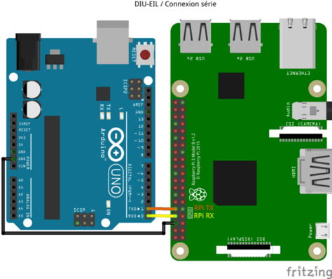
$ minicom -D /dev/ttyACM0 -b 9600 # Arduino avec un microcontrôleur pour interface USB
$ minicom -D /dev/ttyUSB0 -b 9600 # Réplique d'Arduino
# apt install gcc-avr avr-libc avrdude
$ avr-gcc -mmcu=atmega328p -DF_CPU=16000000UL -c -Wall -I. -Os timer.c -o timer.o
$ avr-gcc -mmcu=atmega328p -g -lm -Wl,--gc-sections -o timer.elf timer.o
$ avr-objcopy -j .text -j .data -O ihex timer.elf timer.hex
$ stty -F /dev/ttyACM0 hupcl
$ avrdude -F -v -p atmega328p -c stk500v1 -b 115200 -P /dev/ttyACM0 -U flash:w:timer.hex
export CC = avr-gcc
export LD = avr-gcc
export MCU = atmega328p
export FCPU = 16000000
export TARGET_ARCH = -mmcu=$(MCU)
export CFLAGS = -Wall -I. -DF_CPU=$(FCPU) -Os
export LDFLAGS = -g $(TARGET_ARCH) -lm -Wl,--gc-sections

TERM = /dev/ttyACM0
PGMERISP = -c stk500v1 -b 115200 -P $(TERM)
export DUDE = /usr/bin/avrdude -F -v -p $(MCU)

TARGET = timer
C_SRC = $(wildcard *.c)
OBJS = $(C_SRC:.c=.o)

all: $(TARGET).hex

clean:
        rm -f $(TARGET).o $(TARGET).hex $(TARGET).elf

$(TARGET).elf: $(OBJS)
        $(LD) $(LDFLAGS) -o $@ $(OBJS)

$(TARGET).hex: $(TARGET).elf
        avr-objcopy -j .text -j .data -O ihex $(TARGET).elf $(TARGET).hex

upload: $(TARGET).hex
        stty -F $(TERM) hupcl # reset
        $(DUDE) $(PGMERISP) -U flash:w:$(TARGET).hex

size: $(TARGET).elf
        avr-size --format=avr --mcu=$(MCU) $(TARGET).elf
# apt install dfu-programmer
export CC = avr-gcc
export LD = avr-gcc
export MCU = atmega32u4
export FCPU = 16000000
export FLAGS = -mmcu=$(MCU)
export CFLAGS = -Wall $(FLAGS) -DF_CPU=$(FCPU) -Os
export LDFLAGS = $(FLAGS)

export PROGRAMMER = dfu-programmer

TARGET = pad
SOURCES = $(wildcard *.c)
OBJECTS = $(SOURCES:.c=.o)

all: $(TARGET).hex

clean:
        rm -f *.o $(TARGET).hex $(TARGET)

$(TARGET): $(OBJECTS)

$(TARGET).hex: $(TARGET)
        avr-objcopy -j .text -j .data -O ihex $(TARGET) $(TARGET).hex

upload: $(TARGET).hex
        $(PROGRAMMER) $(MCU) erase
        $(PROGRAMMER) $(MCU) flash $(TARGET).hex
        $(PROGRAMMER) $(MCU) reset

size: $(TARGET)
        avr-size --format=avr --mcu=$(MCU) $(TARGET)
include <stddef.h>
#include <string.h>
#include <avr/io.h>

#include "serial.h"

#define MAX_BUFFER      16

#define getProgramCounter(x)            { asm volatile ( "rcall . \n\t pop r16 \n\t pop r17 \n\t mov %B0, r16 \n\t mov %A0, r17" : "=a" (x) : ); x--; x *= 2; }

char *digits="0123456789ABCDEF";
int base=10;
unsigned int number=0;
unsigned int save=0;
char buffer[MAX_BUFFER+1];
void *next;

int main(void)
{
buffer[MAX_BUFFER]='\0';

goto start;

number_put:
if(base>strlen(digits)) goto *next;
char *p=buffer+MAX_BUFFER;
unsigned int copy=number;
_number_put:
int digit=copy%base;
*--p=digits[digit];
copy /= base;
if(copy && p>buffer) goto _number_put;
serial_print(p);
goto *next;

start:
getProgramCounter(save);

serial_init(9600);
serial_print("Understanding Program Counter!\n");
base=16;
goto print_start_label;

print_start_label:
number=2*(unsigned int)&&start;
next=&&print_start_PC;
goto number_put;

print_start_PC:
serial_print("\n");
number=save;
next=&&print_proc;
goto number_put;

print_proc:
serial_print("\n");
number=2*(unsigned int)&&number_put;
next=&&print_end;
goto number_put;

print_end:
serial_print("\n");
number=2*(unsigned int)&&end;
next=&&end;
goto number_put;

end:
serial_print("\n");

return 0;
}
#include <stddef.h>
#include <string.h>
#include <avr/io.h>

#include "serial.h"

#define MAX_BUFFER      16

static char *digits="0123456789ABCDEF";

void number_put(unsigned int number,int base){
char buffer[MAX_BUFFER+1];
buffer[MAX_BUFFER]='\0';
if(base>strlen(digits)) return;
char *p=buffer+MAX_BUFFER;
unsigned int copy=number;
do{
  int digit=copy%base;
  *--p=digits[digit];
  copy /= base;
  } while(copy && p>buffer);
serial_print(p);
return;
}

void first_proc(int a){
serial_print("\nfirst function a parameter: ");
number_put(a,10);
serial_print("\nSP in first function: ");
number_put(SP,16);
if(a>0) first_proc(a-1);
return;
}

struct big{
  long int a,b,c,d,e,f;
  };

void second_proc(struct big b){
serial_print("\nSP in second function: ");
number_put(SP,16);
return;
}

int main(void)
{
serial_init(9600);
serial_print("\n\n\nUnderstanding Stack Pointer!");
serial_print("\nSP at main begin: ");
number_put(SP,16);
first_proc(0);
struct big param;
second_proc(param);
first_proc(5);
serial_print("\nSP at main end: ");
number_put(SP,16);
serial_print("\n");
return 0;
}
int main(void)
{
buffer[MAX_BUFFER]='\0';

goto start;

number_get:
if(base>strlen(digits)) goto *next;
number=0;
_number_get:
char c=serial_get();
char *f=strchr(digits,c);
int pos=f?f-digits:-1;
if(f==NULL || pos>=base) goto *next;
number *= base;
number += pos;
serial_put(c);
goto _number_get;

number_put:
if(base>strlen(digits)) goto *next;
char *p=buffer+MAX_BUFFER;
unsigned int copy=number;
_number_put:
int digit=copy%base;
*--p=digits[digit];
copy /= base;
if(copy && p>buffer) goto _number_put;
serial_print(p);
goto *next;

start:
serial_init(9600);
serial_print("Addition Calculator\n");
goto read_first_number;

read_first_number:
serial_print("first number: ");
next=&&read_second_number;
goto number_get;

read_second_number:
op1=number;
serial_print("\nsecond number: ");
next=&&make_addition;
goto number_get;

make_addition:
op2=number;
number=op1+op2;
serial_print("\naddition: ");
next=&&end;
goto number_put;

end:
serial_print("\n");

return 0;
}
int number_get(int base){
if(base>strlen(digits)) return 0;
int number=0;
while(1){
  char c=serial_get();
  char *f=strchr(digits,c);
  int pos=f?f-digits:-1;
  if(f==NULL || pos>=base) break;
  number *= base;
  number += pos;
  serial_put(c);
  }
return number;
}

void number_put(unsigned int number,int base){
if(base>strlen(digits)) return;
if(number){
  int digit=number%base;
  number_put(number/base,base);
  serial_put(digits[digit]);
  }
return;
}

int main(void)
{
serial_init(9600);
serial_print("Addition Calculator\n");
serial_print("first number: ");
unsigned int op1=number_get(BASE);
serial_print("\nsecond number: ");
unsigned int op2=number_get(BASE);
unsigned int result=op1+op2;
serial_print("\naddition: ");
number_put(result,BASE);
serial_print("\n");
return 0;
}
int main(void)
{
unsigned int op1,op2;
stdio_init(9600);
printf("Addition Calculator\n");
printf("first number: ");
scanf("%d",&op1);
printf("\nsecond number: ");
scanf("%d",&op2);
unsigned int result=op1+op2;
printf("\naddition: %d\n",result);
return 0;
}
MULS r10,r11
#include <avr/io.h>

void wdt_signaler(void){
asm volatile ("wdr");                      // Réinitialisation du minuteur
}

void wdt_activer(unsigned char prescaler){
cli();
wdt_signaler();
WDTCSR |= (1<<WDCE) | (1<<WDE);            // Demande d'une modification du minuteur
WDTCSR = (1<<WDE) | (0<<WDEI) | prescaler; // Multiplicateur de 0x00 à 0x09
                                           // Génération d'une réinitialisation du CPU
sei();
}

void wdt_desactiver(void){
cli();
wdt_signaler();
__disable_interrupt();
MCUSR &= ~(1<<WDRF);                       // Désactivation d'un déclenchement du minuteur
WDTCSR |= (1<<WDCE) | (1<<WDE);            // Demande d'une modification du minuteur
WDTCSR = 0x00;                             // Désactivation complète du minuteur
sei();
}

int main(void){
wdt_activer((0<<WDP3)|(1<<WDP2)|(1<<WPD1)|(1<<WPD0)); // Minuteur à environ 2s
while(1){
  // faire quelque chose en quelques ms
  wdt_signaler();
  }
}
#include <avr/wdt.h>
#include <avr/sleep.h>

int main(void){
wdt_disable();                             // Désactivation du minuteur au réveil
...                                        // Code pour faire ce qu'il y a faire
wdt_enable(WDTO_2S);                       // Réveil prévu dans environ 2 secondes
set_sleep_mode(SLEEP_MODE_PWR_DOWN);       // Mode sommeil profond
sleep_mode();                              // Zoup au dodo
}
#include <avr/wdt.h>
#include <avr/sleep.h>

int main(void){
wdt_disable();                             // Désactivation du minuteur au réveil
...                                        // Code pour faire ce qu'il y a faire
wdt_enable(WDTO_2S);                       // Réveil prévu dans environ 2 secondes

SMCR &= ~(1<<SM2);
SMCR |= (1<<SM1);
SMCR &= ~(1<<SM0);
SMCR |= (1<<SE);
asm volatile("sleep");
SMCR &= ~(1<<SE);
}
avrdude -c stk500v1 -p atmega328p -P /dev/ttyUSB0 -b 19200 -U lfuse:w:0x62:m
avrdude -c stk500v1 -p atmega328p -P /dev/ttyUSB0 -b 19200 -U lfuse:w:0x4E:m
CLKSEL0 = 0b00010101;   // sélection de l'horloge externe
CLKSEL1 = 0b00001111;   // minimum de 8Mhz
CLKPR = 0b10000000;     // modification du diviseur d'horloge (CLKPCE=1)
CLKPR = 0;              // 0 pour pas de diviseur (diviseur de 1)
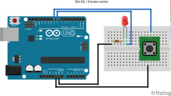
const int LED=8;
const int BOUTON=9;
void setup(){
pinMode(LED,OUTPUT); // Sortie pour la LED
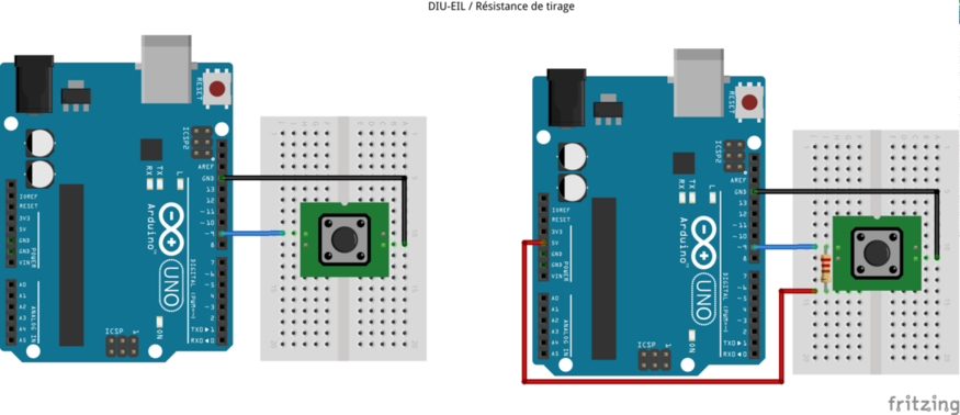
pinMode(BOUTON,INPUT_PULLUP); // Entrée pour le bouton (résistance de tirage)
}
void loop(){
int etat=digitalRead(BOUTON); // Lecture de l'état du bouton
if(etat==HIGH) digitalWrite(LED,LOW); // LED éteinte
else digitalWrite(LED,HIGH); // LED allumée
}
#include <avr/io.h>

#define LED     PB0
#define BOUTON  PB1

int main(void){
DDRB |= (0x01<<LED);         // Sortie pour la LED
DDRB &= ~(0x01<<BOUTON);     // Entrée pour le bouton
PORTB |= (0x01<<BOUTON);     // Configuration de la résistance de tirage

while(1){
  if(PINB & (0x01<<BOUTON)) PORTB &= ~(0x01<<LED);      // LED éteinte
  else PORTB |= (0x01<<LED);                            // LED allumée
  }
}
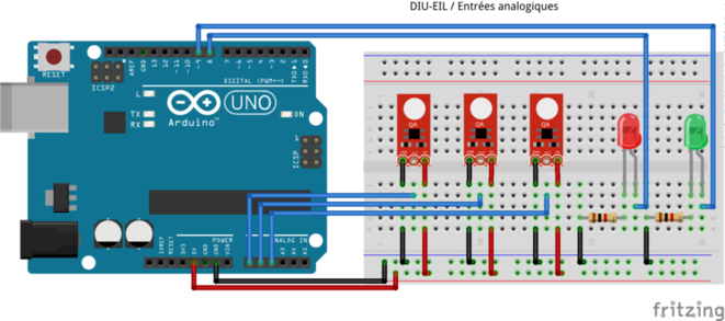
const int LED_G=8;
const int LED_D=9;
const int LIGNE_G=A0;
const int LIGNE_M=A1;
const int LIGNE_D=A2;

const int LIMITE=128;

void setup(){
pinMode(LED_G,OUTPUT);
pinMode(LED_D,OUTPUT);
}

void loop(){
int lg=analogRead(LIGNE_G);             // Valeurs des détecteurs de ligne
int lm=analogRead(LIGNE_M);
int ld=analogRead(LIGNE_D);
if(lg<LIMITE) digitalWrite(LED_D,HIGH); // Ligne perdue à gauche, tourner à droite
if(ld<LIMITE) digitalWrite(LED_G,HIGH); // Ligne perdue à droite, tourner à gauche
if(lm<LIMITE){                          // Sur la ligne continuer tout droit
  digitalWrite(LED_D,LOW);
  digitalWrite(LED_G,LOW);
  }
}
#include <avr/io.h>

#define ADFR 5
#define LIMITE 64

void ad_init(unsigned char channel){    // Sélectionne un canal
ADCSRA |= (1<<ADPS2)|(1<<ADPS1)|(1<<ADPS0); // Division de fréquence 128 => 125KHz
ADCSRA &= ~(1<<ADFR);                       // Mode conversion unique
ADMUX |= (1<<REFS0)|(1<<ADLAR);             // Référence de mesure AVCC
ADMUX=(ADMUX&0xf0)|channel;             // Selection du canal
ADCSRA|=(1<<ADEN);                      // Convertisseur activé
}

unsigned int ad_capture(void){          // Acquisition de tension
ADCSRA|=(1<<ADSC);                      // Début de conversion
while(bit_is_set(ADCSRA, ADSC));        // Attente de la fin de conversion
return ADCH;                            // Résultat sur 8 bits car ADLAR=1
}

int main(void){
DDRB |= 0x03;
int lg,lm,ld;
while(1){
  ad_init(0); lg=ad_capture();
  ad_init(1); lm=ad_capture();
  ad_init(2); ld=ad_capture();
  if(lg<LIMITE) PORTB |= 0x02; // Ligne perdue à gauche, tourner à droite
  if(ld<LIMITE) PORTB |= 0x01; // Ligne perdue à droite, tourner à gauche
  if(lm<LIMITE) PORTB &= ~0x03;  // Sur la ligne continuer tout droit
  }
}
void setup(){
  Serial.begin(9600); // configuration de la vitesse
}

void loop(){
  while(1){           // il y a de l'écho
    if(Serial.available()){  // un octet disponible ?
      int c=Serial.read();   // lecture de l'octet reçu
      Serial.write(c);       // envoi d'un octet
    }
}
#include <avr/io.h>

void serie_init(long int vitesse){
UBRR0=F_CPU/(((unsigned long int)vitesse)<<4)-1; // configure la vitesse
UCSR0B=(1<<TXEN0 | 1<<RXEN0);                    // autorise l'envoi et la réception
UCSR0C=(1<<UCSZ01 | 1<<UCSZ00);                  // 8 bits et 1 bit de stop
UCSR0A &= ~(1 << U2X0);                          // double vitesse désactivée
}

void serie_envoyer(unsigned char c){
loop_until_bit_is_set(UCSR0A,UDRE0);
UDR0=c;
}

unsigned char serie_recevoir(void){
loop_until_bit_is_set(UCSR0A, RXC0);
return UDR0;
}

int main(void){
serie_init(9600);
while(1){
  unsigned char c=serie_recevoir();
  serie_envoyer(c);
  }
return 0;
}
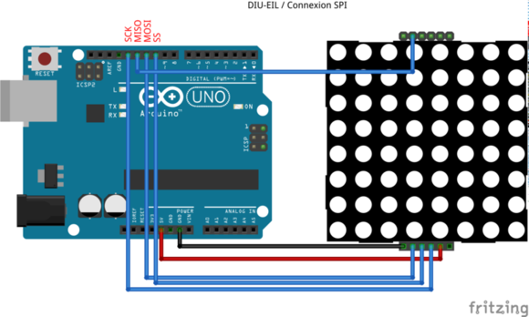
#include <SPI.h>

void setup(void){
SPI.begin();                            // Initialisation SPI
SPI.setClockDivider(SPI_CLOCK_DIV8);    // Horloge F_CPU/64
digitalWrite(SS,HIGH);                  // Désactive le périphérique
}

void loop(void){
digitalWrite(SS,LOW);
for(i=0;i<64;i++) SPI.transfer(0xe0);
digitalWrite(SS,HIGH);
}
#include <avr/io.h>

#define SPI_DDR         DDRB
#define SPI_PORT        PORTB
#define SPI_SS          2
#define SPI_MOSI        3
#define SPI_MISO        4
#define SPI_SCK         5

void spi_init(void){                                 // Initialisation du bus SPI
SPI_DDR |= (1<<SPI_MOSI)|(1<<SPI_SCK)|(1<<SPI_SS);   // Définition des sorties
SPI_DDR &= ~(1<<SPI_MISO);                           // Définition de l'entrée
SPI_PORT |= (1<<SPI_SS);                             // Désactivation du périphérique
SPCR = (1<<SPE)|(1<<MSTR)|(1<<SPR1);                 // Activation SPI (SPE) en état maître (MSTR)
                                                     // horloge F_CPU/64 (SPR1=1,SPR0=0)
}

void spi_activer(void){                              // Activer le périphérique
SPI_PORT &= ~(1<<SPI_SS);                            // Ligne SS à l'état bas
}

void spi_desactiver(void){                           // Désactiver le périphérique
SPI_PORT |= (1<<SPI_SS);                             // Ligne SS à l'état haut
}

uint8_t spi_echange(uint8_t envoi){                  // Communication sur le bus SPI
SPDR = envoi;                                        // Octet a envoyer
while(!(SPSR & (1<<SPIF)));                          // Attente fin envoi (drapeau SPIF du statut)
return SPDR;                                         // Octet reçu
}

int main(void){
spi_init();
int i;
spi_activer();
for(i=0;i<64;i++) spi_echange(0xe0);                 // Que de rouge
spi_desactiver();
}
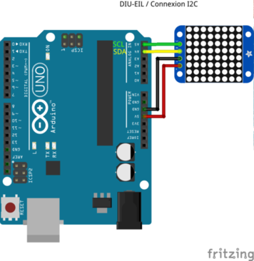
#define MATRICE_REG_LUMINE      0xE0
#define MATRICE_SYSTEME         0x20
#define MATRICE_AFFICHAGE       0x80
#define MATRICE_ADR_I2C         0x70

void luminosite(uint8_t adr_i2c,uint8_t lum){
if(lum>15) lum=15;
Wire.beginTransmission(adr_i2c);
Wire.write(MATRICE_REG_LUMINE|lum);
Wire.endTransmission();
}

void matrice_init(uint8_t adr_i2c){
Wire.begin();
Wire.setClock(400000UL);
Wire.beginTransmission(adr_i2c);
Wire.write(MATRICE_SYSTEME|1);    // Démarre l'horloge
Wire.endTransmission();
Wire.beginTransmission(adr_i2c);
Wire.write(MATRICE_AFFICHAGE|1);  // Alimente les LED
}

void matrice_afficher(uint8_t adr_i2c,uint8_t image[8]){
Wire.beginTransmission(i2c_addr);
Wire.write((uint8_t)0x00);        // Adresse de départ
for(uint8_t i=0;i<8;i++){
  Wire.write(image[i]);
  Wire.write(0);
  }
Wire.endTransmission();
}
#include <avr/io.h>

#define         ERROR   0
#define         SUCCESS 1

#define         IIC_START       0x08
#define         IIC_RESTART     0x10
#define         IIC_WADDR_ACK   0x18
#define         IIC_WDATA_ACK   0x28
#define         IIC_RADDR_ACK   0x40
#define         IIC_RDATA_ACK   0x50
#define         IIC_RDATA_NACK  0x58

#define         SCL_CLOCK       400000L // En Hertz

void i2c_init(void){
TWSR=0;                          // Pas de multiplicateur d'horloge
TWBR=((F_CPU/SCL_CLOCK)-16)/2;   // Fréquence de l'horloge i2c
TWCR=(1<<TWEN);                  // Activation de l'i2c matériel
}

static void i2c_start(void){     // Envoi d'un start
TWCR=(1<<TWINT)|(1<<TWSTA)|(1<<TWEN);
while((TWCR & (1<<TWINT))==0);   // Attente de fin d'envoi
}

static void i2c_stop(void){      // Envoi d'un stop
TWCR=(1<<TWINT)|(1<<TWSTO)|(1<<TWEN);
}

static uint8_t i2c_statut(void){ // Etat de la dernière transmission
return (TWSR & 0xF8);
}

void i2c_ecrire(uint8_t octet){  // Envoi d'un octet sur le bus i2c
TWDR=octet;                      // Ecriture de l'octet à envoyer
TWCR=(1<<TWINT)|(1<<TWEN);
while((TWCR & (1<<TWINT))==0);   // Attente de fin d'envoi
}

uint8_t i2c_lire_ack(void){      // Lecture d'un octet sur i2c avec accusé positif
TWCR=(1<<TWINT)|(1<<TWEN)|(1<<TWEA);
while((TWCR & (1<<TWINT))==0);
return TWDR;
}

uint8_t i2c_lire_nack(void){     // Lecture d'un octet sur i2c avec accusé négatif
TWCR=(1<<TWINT)|(1<<TWEN);
while((TWCR & (1<<TWINT))==0);
return TWDR;
}

uint8_t i2c_ecrire_registre(uint8_t adr_i2c,uint8_t reg_val,unsigned char stop){
                                 // Modification de la valeur d'un registre
int statut;
i2c_start();
statut=i2c_statut(); if(status!=IIC_START && status!=IIC_RESTART) return ERROR;
i2c_ecrire(adr_i2c<<1);
statut=i2c_statut(); if(status!=IIC_WADDR_ACK) return ERROR;
i2c_ecrire(reg_val);
statut=i2c_statut(); if(status!=IIC_WDATA_ACK) return ERROR;
if(stop) i2c_stop();
return SUCCESS;
}

uint8_t i2c_ecrire_donnee(uint8_t adr_i2c,uint8_t adresse,uint8_t donnee){
                                 // Ecriture dans la mémoire de l'esclave
int statut;
i2c_start();
statut=i2c_statut(); if(status!=IIC_START && status!=IIC_RESTART) return ERROR;
i2c_ecrire(adr_i2c<<1);
statut=i2c_statut(); if(status!=IIC_WADDR_ACK) return ERROR;
i2c_ecrire(reg_val);
statut=i2c_statut(); if(status!=IIC_WDATA_ACK) return ERROR;
i2c_ecrire(donnee);
statut=i2c_statut(); if(status!=IIC_WDATA_ACK) return ERROR;
TWI_stop();
return SUCCESS;
}

#define MATRICE_REG_LUMINE      0xE0
#define MATRICE_SYSTEME         0x20
#define MATRICE_AFFICHAGE       0x80
#define MATRICE_ADR_I2C         0x70

int matrice_afficher(uint8_t image[8]){
int dim=0x01;                   // Ecriture de quelques registres de la matrice
i2c_ecrire_registre(MATRICE_ADR_I2C,MATRICE_SYSTEME|1,1);
i2c_ecrire_registre(MATRICE_ADR_I2C,MATRICE_REG_LUMINE|dim,1);
i2c_ecrire_registre(MATRICE_ADR_I2C,MATRICE_AFFICHAGE|1,1);
int i;                          // Envoi de chaque ligne
for(i=0;i<8;i++) i2c_ecrire_donnee(MATRICE_ADR_I2C,2*i,image[i]);
return 0;
}
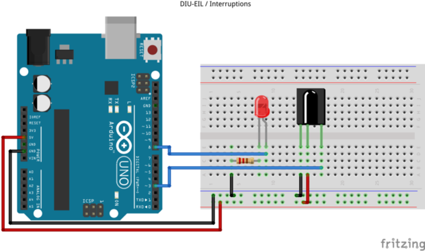
const byte LED=8;
const byte INT=3;
int etat=LOW;

void clignote(){            // Procédure d'interruption
etat=(etat==LOW)?HIGH:LOW;
digitalWrite(LED,etat);
}

void setup(){
pinMode(LED,OUTPUT);        // Sortie pour la LED
pinMode(INT,INPUT);         // Entrée pour le détecteur infrarouge
attachInterrupt(digitalPinToInterrupt(INT),clignote,CHANGE);
}

void loop(){}               // Rien dans la boucle principale
#include <avr/io.h>
#include <avr/interrupt.h>

#define INT_BAS         0
#define INT_CHANGE      1
#define INT_DESCENTE    2
#define INT_MONTEE      3

void interruption_init        // Initialisation d'interruption
   (uint8_t num,uint8_t mode){
uint8_t isc0=0,isc1=0;
switch(mode){
  case INT_BAS:               // Interruption sur niveau bas
    isc0=0; isc1=0; break;
  case INT_CHANGE:            // Interruption sur changement d'état
    isc0=1; isc1=0; break;
  case INT_DESCENTE:          // Interruption sur front descendant
    isc0=0; isc1=1; break;
  case INT_MONTEE:            // Interruption sur front montant
    isc0=1; isc1=1; break;
  }
if(num==0){                   // Configuration pour INT0
  EICRA |= (isc1<<ISC01)|(isc0<<ISC00);
  EIMSK |= (1<<INT0);
  }
if(num==1){                   // Configuration pour INT1
  EICRA |= (isc1<<ISC11)|(isc0<<ISC10);
  EIMSK |= (1<<INT1);
  }
}

ISR(INT1_vect){               // Procédure d'interruption
PORTB ^= 0x01; }

int main(void){
DDRB |= 0x01;
DDRD &= ~0x08;

interruption_init(1,INT_CHANGE);
sei();                        // Autorisation des interruptions
while(1);
return 0;
}
#include <avr/io.h>
#include <avr/interrupt.h>
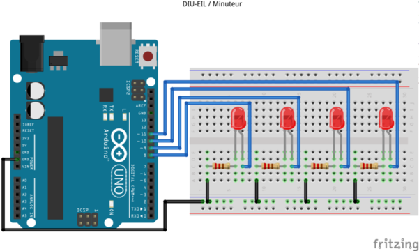
#define CTC1 WGM12 // Meilleur nom pour le bit
#define PERIODE 1000
void init_minuteur(int diviseur,long periode){
TCCR1A=0; // Le mode choisi n'utilise pas ce registre
TCCR1B=(1<<CTC1); // Réinitialisation du minuteur sur expiration
switch(diviseur){
case 8: TCCR1B |= (1<<CS11); break;
case 64: TCCR1B |= (1<<CS11 | 11<<CS10); break;
case 256: TCCR1B |= (1<<CS12); break;
case 1024: TCCR1B |= (1<<CS12 | 1<<CS10); break;
}
// Un cycle prend 1/F_CPU secondes.
// Un pas de compteur prend diviseur/F_CPU secondes.
// Pour une periode en millisecondes, il faut (periode/1000)/(diviseur/F_CPU) pas
// soit (periode*F_CPU)/(1000*diviseur)
OCR1A=F_CPU/1000*periode/diviseur; // Calcul du pas
TCNT1=0; // Compteur initialisé
TIMSK1=(1<<OCIE1A); // Comparaison du compteur avec OCR1A
}
ISR(TIMER1_COMPA_vect){ // Procédure d'interruption
int led=(PINB&0x0f);
led >>= 1; if(led==0) led=0x08;
PORTB &= 0xf0; PORTB |= led;
}
int main(void){
DDRB |= 0x0f; // Chenillard sur 4 LED
PORTB &= ~0x0f; // LED éteintes
init_minuteur(256,PERIODE);
sei();
while(1);
}
#include <avr/io.h>

void ad_init(unsigned char channel){
ADCSRA = (1<<ADPS2) | (1<<ADPS1) | (1<<ADPS0); // Résolution maximale
ADCSRB = (((channel&0x20)==0?0:1)<<MUX5); // Sélection du canal
ADMUX  = channel&0x1f;
ADMUX  |= (0<<REFS1) | (1<<REFS0);  // Référence de mesure AVCC
ADMUX  |= (1<<ADLAR);    // Alignement gauche de la valeur
ADCSRA |= (1<<ADEN);    // Convertisseur activé
}

unsigned int ad_capture(void){
ADCSRA |= (1<<ADSC);    // Début de conversion
while(ADCSRA & (1<<ADSC));   // Attente de la fin de conversion
return ADCH;     // Un seul octet retourné
}
#include <stdint.h>
#include <avr/io.h>

#define SPI_DDR         DDRB
#define SPI_PORT        PORTB
#define SPI_SS          0
#define SPI_SCK         1
#define SPI_MOSI        2
#define SPI_MISO        3

void spi_init(void){                                 // Initialisation du bus SPI
{
SPI_DDR |= (1<<SPI_MOSI)|(1<<SPI_SCK)|(1<<SPI_SS);
SPI_DDR &= ~(1<<SPI_MISO);
SPI_PORT |= (1<<SPI_SS);
SPI_PORT |= (1<<SPI_MISO);
SPSR = (1<<SPI2X);
SPCR = (1<<SPE)|(1<<MSTR)|(1<<CPOL)|(1<<CPHA);
}

void spi_activer(void){                              // Activer le périphérique
SPI_PORT &= ~(1<<SPI_SS);                            // Ligne SS à l'état bas
}

void spi_desactiver(void){                           // Désactiver le périphérique
SPI_PORT |= (1<<SPI_SS);                             // Ligne SS à l'état haut
}

uint8_t spi_echange(uint8_t envoi){                  // Communication sur le bus SPI
{
SPDR = envoi;
while(!(SPSR & (1<<SPIF)));
return SPDR;
}
#include <avr/io.h>
#include <util/delay.h>

#define DTH_ERR_TIMEOUT         -1
#define DTH_ERR_CHECKSUM        -2

typedef struct{
  int temperature;
  int humidity ;
  } dht_values;

#define DTH_DDR         DDRD
#define DTH_PORT        PORTD
#define DTH_PIN         PIND
#define DTH_IO          7

#define DTH_ANSWER_SIZE 40
#define DTH_TIMEOUT     (F_CPU/40000)  // 2,5 ms

#define DTH_WAIT_LOW_MS         20
#define DTH_WAIT_HIGH_US        40
#define DTH_LOOP_CYCLES         2
#define DTH_HIGH_DELAY_US       40

static void dht_trigger(void){
uint8_t mask=(1<<DTH_IO);
DTH_DDR |= mask;
DTH_PORT &= ~mask;
_delay_ms(DTH_WAIT_LOW_MS);
DTH_PORT |= mask;
_delay_us(DTH_WAIT_HIGH_US);
DTH_DDR &= ~mask;
}

int dht_get(dht_values *values){
uint8_t bits[DTH_ANSWER_SIZE/8];
int i,l;
dht_trigger();                   // Trigger answer
uint8_t mask=(1<<DTH_IO);        // Check acknowledgment
for(l=DTH_TIMEOUT;l>=0 && (DTH_PIN&mask)==0;l--); if(l<0) return DTH_ERR_TIMEOUT;
for(l=DTH_TIMEOUT;l>=0 && (DTH_PIN&mask)!=0;l--); if(l<0) return DTH_ERR_TIMEOUT;
for(i=0;i<DTH_ANSWER_SIZE;i++){  // Read values
  if(i%8==0) bits[i/8]=0;
  for(l=DTH_TIMEOUT;l>=0 && (DTH_PIN&mask)==0;l--); if(l<0) return DTH_ERR_TIMEOUT;
  for(l=DTH_TIMEOUT;l>=0 && (DTH_PIN&mask)!=0;l--); if(l<0) return DTH_ERR_TIMEOUT;
  uint32_t time=l*DTH_LOOP_CYCLES/(F_CPU/1000000L);
  bits[i/8] <<= 1;
  if(time<DTH_HIGH_DELAY_US) bits[i/8] |= 0x01;
  }
uint8_t sum=bits[0]+bits[2];     // Verify checksum
if(sum!=bits[4]) return DTH_ERR_CHECKSUM;
values->humidity=bits[0];        // Convert values
values->temperature=bits[2];
return 0;
}
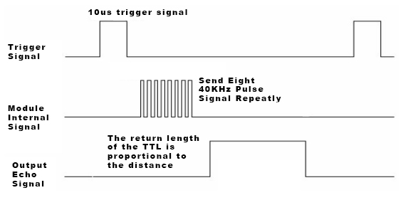
const int LED=13;
const int trigger=2;
const int echo=3;

void setup(){
pinMode(trigger,OUTPUT); // Broche pour activer la mesure (sortie)
pinMode(echo,INPUT);     // Broche pour lire la valeur (entrée)
pinMode(LED,OUTPUT);
}

void loop(){
digitalWrite(trigger,LOW);  delayMicroseconds(5);  // Activer
digitalWrite(trigger,HIGH); delayMicroseconds(10);
digitalWrite(trigger,LOW);

long duree=pulseIn(echo,HIGH);                     // Mesurer
long distance=(duree/2)/29.1;

if(distance<20) digitalWrite(LED,HIGH);            // Réagir
else digitalWrite(LED,LOW);
delay(500);
}
#include <avr/io.h>
#include <util/delay.h>

#define US_DDR          DDRD
#define US_PORT         PORTD
#define US_PIN          PIND
#define US_TRIGGER      2
#define US_ECHO         3

void sonar_init(void){          // Initialiser le sonar
US_DDR |= (1<<US_TRIGGER);   // Broche pour activer la mesure (sortie)
US_DDR &= ~(1<<US_ECHO);     // Broche pour lire la valeur (entrée)
}

uint32_t sonar_mesure(void){    // Mesurer une distance
uint8_t statut=0;
uint32_t temps=0;
_delay_us(2);  US_PORT |= (1<<US_TRIGGER);    // Activer
_delay_us(10); US_PORT &= ~(1 << US_TRIGGER);
while(!statut){
  while(US_PIN&(1<<US_ECHO)){                 // Mesure la durée du signal haut
    temps++;
    statut=1;
    }
  }
return temps*0.00862;                     // Conversion en cm
}
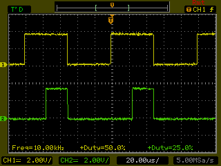
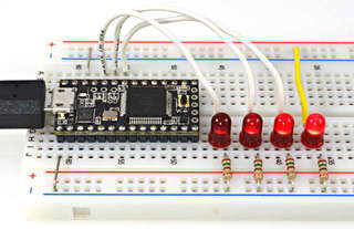
const int LED=8;

void setup(void){
for(int i=0;i<4;i++) pinMode(LED+i,OUTPUT);
for(int i=0;i<4;i++) analogWrite(LED+i,(100-25*i)*255/100);
}

void loop(void){ }
#include <avr/io.h>

#define PWM_DDR         DDRD
#define PWM_PORT        PORTD
#define PWM1            5
#define PWM2            6

void PWM_init(void){               // Initialisation de la PWM
PWM_DDR |= (1<<PWM1)|(1<<PWM2);      // Les ports PWM sont des sorties
TCCR0A |= (1<<COM0A1)|(1<<COM0B1);   // Les ports PWM se comportent normalement
TCCR0A |= (1<<WGM01)|(1<<WGM00);     // Minuteur mis en mode PWM
TCCR0B |= (1<<CS00);                 // Pas de pré-diviseur, démarre le compteur
}

int main(void){
PWM_init();
int pwm=0;
while(1){
  pwm++; if(pwm>100) pwm=0;
  OCR0A=pwm*255/100;                 // PWM pour le port 5 (ramenée à 255)
  OCR0B=(100-pwm)*255/100;           // PWM pour le port 6 (ramenée à 255)
  _delay_ms(10);
  }
return 0;
}
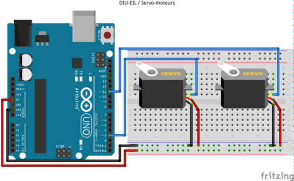
#include <Servo.h>

const int SERVO=3;

Servo myservo;            // Objet servo

void setup(){
  myservo.attach(SERVO);  // Définit la broche du servo-moteur
}

void loop(){
for(pos=0;pos<=180;pos += 1){
  myservo.write(pos);     // Impose la position (en degrés) au servo
  delay(15);
  }
for(pos=180;pos>=0;pos -= 1){
  myservo.write(pos);
  delay(15);
  }
}
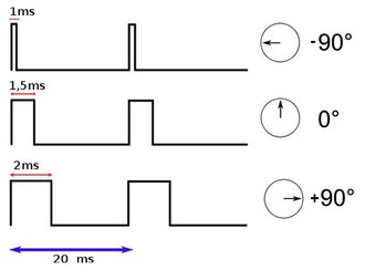
#include <avr/io.h>
#include <util/delay.h>

void servos_init(void){
DDRD |= 0x08; // La broche 3 du port D est controlée par le minuteur 2
DDRB |= 0x08; // La broche 3 du port B est controlée par le minuteur 2
TCCR2A=(1<<COM2A1)|(1<<COM2B1);      // COM2A et COM2B à 10 pour signaux normaux
TCCR2A |= (1<<WGM21) | (1<<WGM20);   // WGM2 à 011 pour mode "fast PWM"
TCCR2B = (1<<CS21) | (1<<CS22);      // CS2 à 110 pour un pré-diviseur de 256
// Une unité de OCR2A et OCR2B représente donc 256/16000000*1000*1000=16 us
// Pour un plateau de 1ms il faut alors 62 unités
// Pour un plateau de 2ms il faut alors 125 unités
}

int main(void){
int a;
servos_init();
for(a=0;a<180;a++){ OCR2A=62+a*63/180; _delay_ms(10); }
for(a=180;a>0;a--){ OCR2A=62+a*63/180; _delay_ms(10); }
}
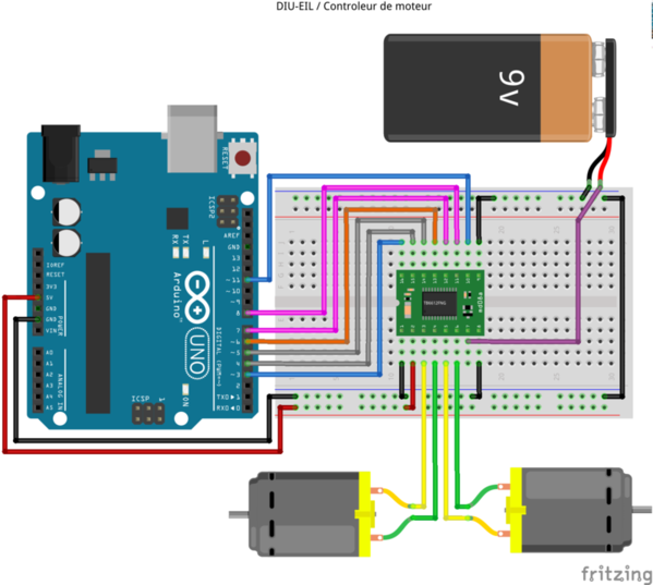
const int STANDBY=6;
const int PWMA=3;
const int AIN1=5;
const int AIN2=4;
const int PWMB=11;
const int BIN1=7;
const int BIN2=8;
const int broches[]={STANDBY,PWMA,AIN1,AIN2,PWMB,BIN1,BIN2,-1};

void setup(void){
int i=0; while(broches[i]>0) pinMode(broches[i++],OUTPUT);
digitalWrite(STANDBY,HIGH);     // Activation du contrôleur
digitalWrite(AIN1,HIGH);        // Les moteurs dans le même sens
digitalWrite(AIN2,LOW);
digitalWrite(BIN1,HIGH);
digitalWrite(BIN2,LOW);
analogWrite(PWMA,128);          // Vitesse modérée
analogWrite(PWMB,128);
}

void loop(void){ }
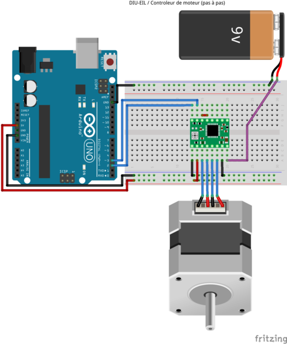
const int DIR=2;
const int STEP=3;
const int CYCLE=200;

void setup(void){
pinMode(DIR,OUTPUT);
pinMode(STEP,OUTPUT);
}

void loop(void){
digitalWrite(DIR,HIGH);
for(int pas=0;pas<CYCLE;pas++){
  digitalWrite(STEP,HIGH);
  delayMicroseconds(2000);
  digitalWrite(STEP,LOW);
  delayMicroseconds(2000);
  }
delay(1000);
}
| Classe | Description | Exemple |
| 00h | Inconnu | Spécifique |
| 01h | Audio | Carte son |
| 02h | Communications | Carte réseau |
| 03h | Human interface device (HID) | Clavier |
| 05h | Physical Interface Device (PID) | Equipement à retour de force |
| 06h | Image | Webcam |
| 07h | Printer | Imprimante |
| 08h | Mass storage | Clef USB |
| 09h | USB hub | Répéteur USB |
| 0Bh | Smart Card | Lecteur de carte |
| 0Dh | Content security | Lecteur d’empreinte digitale |
| 0Eh | Video | Webcam |
| 0Fh | Personal Healthcare | Tensiomètre |
| E0h | Wireless Controller | Adaptateur Bluetooth |

# lsusb
Bus 001 Device 001: ID 1d6b:0002 Linux Foundation 2.0 root hub
Bus 002 Device 001: ID 1d6b:0002 Linux Foundation 2.0 root hub
Bus 001 Device 002: ID 8087:0020 Intel Corp. Integrated Rate Matching Hub
Bus 002 Device 002: ID 8087:0020 Intel Corp. Integrated Rate Matching Hub
Bus 001 Device 003: ID 13d3:5130 IMC Networks
Bus 001 Device 004: ID 058f:6366 Alcor Micro Corp. Multi Flash Reader
Bus 002 Device 003: ID 05fe:1958 Chic Technology Corp.
Bus 002 Device 004: ID 13fe:1e00 Kingston Technology Company Inc.
 ehci_hcd: USB 2.0 'Enhanced' Host Controller (EHCI) Driver
 ...
 ehci_hcd 0000:00:1a.0: new USB bus registered, assigned bus number 1
 ...
 usb usb1: New USB device found, idVendor=1d6b, idProduct=0002
 ...
 hub 1-0:1.0: USB hub found
 hub 1-0:1.0: 2 ports detected
 ...
 ehci_hcd 0000:00:1d.0: new USB bus registered, assigned bus number 2
 ...
 hub 2-0:1.0: USB hub found
 hub 2-0:1.0: 2 ports detected
 ...
 hub 1-1:1.0: USB hub found
 hub 1-1:1.0: 6 ports detected
 ...
 hub 2-1:1.0: USB hub found
 hub 2-1:1.0: 8 ports detected
 usb 1-1.2: new high speed USB device number 3 using ehci_hcd
 usb 1-1.2: New USB device found, idVendor=13d3, idProduct=5130
 usb 1-1.2: New USB device strings: Mfr=2, Product=1, SerialNumber=0
 usb 1-1.2: Product: USB 2.0 Camera
# lsusb -v -s 1:3
Bus 001 Device 003: ID 13d3:5130 IMC Networks
Device Descriptor:
  bLength                18
  bDescriptorType         1
  bcdUSB               2.00
  bDeviceClass          239 Miscellaneous Device
  bDeviceSubClass         2 ?
  bDeviceProtocol         1 Interface Association
  bMaxPacketSize0        64
  idVendor           0x13d3 IMC Networks
  idProduct          0x5130
  bcdDevice           12.11
  iManufacturer           2 Sonix Technology Co., Ltd.
  iProduct                1 USB 2.0 Camera
  iSerial                 0
  bNumConfigurations      1
...
# ls -d /sys/bus/usb/devices/1-1.2*
/sys/bus/usb/devices/1-1.2 /sys/bus/usb/devices/1-1.2:1.1
/sys/bus/usb/devices/1-1.2:1.0
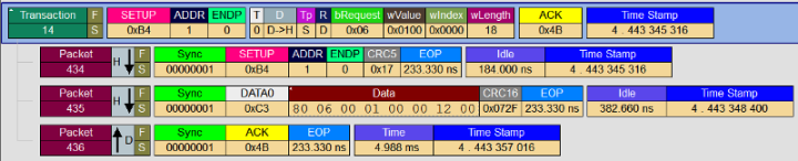
| Type (8 bits) IN|OUT | Adresse (7 bits) | Point d’accès (4 bits) | Somme de contrôle (5 bits) |
| Type (8 bits) DATAx | Données (8 à 1024 octets) | Somme de contrôle (16 bits) |
| Type (8 bits) ACK|NAK|STALL |
libusb_context *context;
int status=libusb_init(&context);
if(status!=0) {perror("libusb_init"); exit(-1);}
/* ... some code ... */
libusb_exit(context);
libusb_device **list;
ssize_t count=libusb_get_device_list(context,&list);
if(count<0) {perror("libusb_get_device_list"); exit(-1);}
ssize_t i=0;
for(i=0;i<count;i++){
  libusb_device *device=list[i];
  struct libusb_device_descriptor desc;
  int status=libusb_get_device_descriptor(device,&desc);
  if(status!=0) continue;
  uint8_t bus=libusb_get_bus_number(device);
  uint8_t address=libusb_get_device_address(device);
  printf("Device Found @ (Bus:Address) %d:%d\n",bus,address);
  printf("Vendor ID 0x0%x\n",desc.idVendor);
  printf("Product ID 0x0%x\n",desc.idProduct);
  }
libusb_free_device_list(list,1);
int status;
struct libusb_config_descriptor *configdesc;
status=libusb_get_active_config_descriptor(device,&configdesc);
if(status!=0){ perror("libusb_get_active_config_descriptor"); exit(-1); }
libusb_device_handle *handle;
int status=libusb_open(device,&handle);
if(status!=0){ perror("libusb_open"); exit(-1); }
/* ... some ... code */
libusb_close(handle);
int status;
int indice=0; /* e.g. première configuration */
struct libusb_config_descriptor *configdesc;
status=libusb_get_config_descriptor(device,indice,&configdesc);
if(status!=0){ perror("libusb_get_config_descriptor"); exit(-1); }
int configuration=configdesc->bConfigurationValue;
status=libusb_set_configuration(handle,configdesc->bConfigurationValue);
if(status!=0){ perror("libusb_set_configuration"); exit(-1); }
int indint=0 /* e.g. première interface */
int indalt=0 /* e.g. première alternative */
int interface=configdesc->interface[indint].altsetting[indalt].bInterfaceNumber;
int status=libusb_claim_interface(handle,interface);
if(status!=0){ perror("libusb_claim_interface"); exit(-1); }
/* ... some code ... */
status=libusb_release_interface(handle,interface);
if(status!=0){ perror("libusb_release_interface"); exit(-1); }
if(libusb_kernel_driver_active(handle,interface)){
  int status=libusb_detach_kernel_driver(handle,interface);
  if(status!=0){ perror("libusb_detach_kernel_driver"); exit(-1); }
  }
int typ=LIBUSB_REQUEST_TYPE_xxx; /* see libusb.h */
int req=LIBUSB_REQUEST_yyy    ;  /* see libusb.h */
int val=...;          /* parameter for req */
int ind=...;          /* parameter for req */
char data[MAX_DATA];  /* data to send or to receive */
int size=...;         /* size to send or maximum size to receive */
int timeout=...;      /* timeout in ms */
int nb_bytes=libusb_control_transfer(handle,typ,req,val,ind,data,size,timeout);
int endpoint_out=...;   /* ID of endpoint (bit 8 is 0) */
int endpoint_in=...;    /* ID of endpoint (bit 8 is 1) */
char data[MAX_DATA];    /* data to send or to receive */
int size=...;           /* size to send or maximum size to receive */
int timeout=...;        /* timeout in ms */
/* OUT interrupt, from host to device */
int bytes_out;
int status=libusb_interrupt_transfer(handle,endpoint_out,data,size,&bytes_out,timeout);
if(status!=0){ perror("libusb_interrupt_transfer"); exit(-1); }
/* IN interrupt, host polling device */
int bytes_in;
int status=libusb_interrupt_transfer(handle,endpoint_in,data,size,&bytes_in,timeout);
if(status!=0){ perror("libusb_interrupt_transfer"); exit(-1); }
int endpoint_out=...;   /* ID of endpoint (bit 8 is 0) */
int endpoint_in=...;    /* ID of endpoint (bit 8 is 1) */
char data[MAX_DATA];    /* data to send or to receive */
int size=...;           /* size to send or maximum size to receive */
int timeout=...;        /* timeout in ms */
/* OUT bulk transfer */
int bytes_out;
int status=libusb_bulk_transfer(handle,endpoint_out,data,size,&bytes_out,timeout);
if(status!=0){ perror("libusb_bulk_transfer"); exit(-1); }
/* IN bulk transfer */
int bytes_in;
int status=libusb_bulk_transfer(handle,endpoint_in,data,size,&bytes_in,timeout);
if(status!=0){ perror("libusb_bulk_transfer"); exit(-1); }
Endpoint_ConfigureEndpoint(<EPADDR>, <EP_TYPE>, <EPSIZE>, 1);
/* Select the IN Endpoint */
Endpoint_SelectEndpoint(IN_EPADDR);
/* Check if Endpoint Ready for Read/Write */
if(Endpoint_IsReadWriteAllowed()){
  /* Write Keyboard Report Data */
  Endpoint_Write_xxx(...);
  /* Finalize the stream transfer to send the last packet */
  Endpoint_ClearIN();
  }
/* Select the OUT Endpoint */
Endpoint_SelectEndpoint(OUT_EPADDR);

/* Check if Endpoint contains a packet */
if(Endpoint_IsOUTReceived()){
  /* Check to see if the packet contains data */
  if(Endpoint_IsReadWriteAllowed()){
    /* Read from the host */
    ... Endpoint_Read_yyy(...);
    /* Process the data from the host */
    ...
    }
  /* Handshake the OUT Endpoint - clear endpoint and ready for next report */
  Endpoint_ClearOUT();
  }
#include <avr/io.h>  // for the input/output register
#include <avr/interrupt.h>

#define PRESCALER 256
#define NB_TICK  12500
#define CTC1  WGM12  // Better name

int led_bit=0x01;

void init_ports(void){
DDRB  |= led_bit;
PORTB |= 0x00;
}

void init_timer(){
TCCR1A = 0;  // No output pin connected, no PWM mode enabled
TCCR1B = 1<<CTC1; // No input pin used, clear timer counter on compare match
#if (PRESCALER==8)
        TCCR1B |= (1<<CS11);
#endif
#if (PRESCALER==64)
        TCCR1B |= (1<<CS11 | 11<<CS10);
#endif
#if (PRESCALER==256)
        TCCR1B |= (1<<CS12);
#endif
#if (PRESCALER==1024)
        TCCR1B |= (1<<CS12 | 1<<CS10);
#endif
OCR1A = NB_TICK;
TCNT1 = 0;
TIMSK1 = (1<<OCIE1A); // No overflow mode enabled, no input interrupt, output compare interrupt
}

ISR(TIMER1_COMPA_vect){
PORTB ^= led_bit;
}

int main(void){
init_ports();
init_timer();
sei();
return 0;
}
$ avr-gcc -E -I. -DF_CPU=16000000 -mmcu=atmega328p -Wp,-P -Os timer.c -o timer-cpp.c
$ cat timer-cpp.c
...
int led_bit=0x01;
void init_ports(void){
(*(volatile uint8_t *)((0x04) + 0x20)) |= led_bit;
(*(volatile uint8_t *)((0x05) + 0x20)) |= 0x00;
}
void init_timer(){
(*(volatile uint8_t *)(0x80)) = 0;
(*(volatile uint8_t *)(0x81)) = 1<<3;
(*(volatile uint8_t *)(0x81)) |= (1<<2);
(*(volatile uint16_t *)(0x88)) = 12500;
(*(volatile uint16_t *)(0x84)) = 0;
(*(volatile uint8_t *)(0x6F)) = (1<<1);
}
void __vector_11 (void) __attribute__ ((signal,used, externally_visible)) ; void __vector_11 (void){
(*(volatile uint8_t *)((0x05) + 0x20)) ^= led_bit;
}
int main(void){
init_ports();
init_timer();
__asm__ __volatile__ ("sei" ::: "memory");
return 0;
}
$ avr-gcc -Wall --dump-tree-all-graph -I. -DF_CPU=16000000 -Os -mmcu=atmega328p -c -o timer.o timer.c
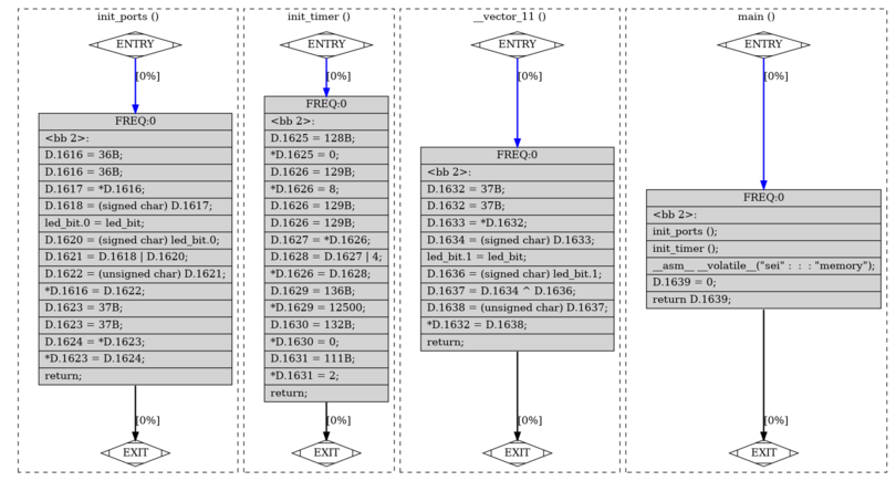
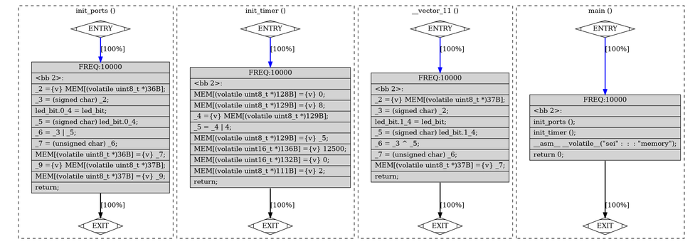
...
;; Function init_ports
(note 1 0 3 NOTE_INSN_DELETED)
(note 3 1 20 [bb 2] NOTE_INSN_BASIC_BLOCK)
(note 20 3 2 NOTE_INSN_PROLOGUE_END)
(note 2 20 6 NOTE_INSN_FUNCTION_BEG)
(insn 6 2 7 (set (reg:QI 25 r25 [orig:42 D.1651 ] [42])
        (mem/v:QI (const_int 36 [0x24]) [0 MEM[(volatile uint8_t *)36B]+0 S1 A8])) timer.c:13 71 {movqi_insn}
     (nil))
(note 7 6 8 NOTE_INSN_DELETED)
(insn 8 7 9 (set (reg:QI 24 r24 [orig:51 led_bit ] [51])
        (mem/c:QI (symbol_ref:HI ("led_bit") [flags 0x2]  <var_decl 0x7f6d24cf8cf0 led_bit>) [1 led_bit+0 S1 A8])) timer.c:13 71 {movqi_insn}
     (nil))
(insn 9 8 11 (set (reg:QI 24 r24 [orig:47 D.1651 ] [47])
        (ior:QI (reg:QI 24 r24 [orig:51 led_bit ] [51])
            (reg:QI 25 r25 [orig:42 D.1651 ] [42]))) timer.c:13 266 {iorqi3}
     (expr_list:REG_DEAD (reg:QI 25 r25 [orig:42 D.1651 ] [42])
        (nil)))
(insn 11 9 13 (set (mem/v:QI (const_int 36 [0x24]) [0 MEM[(volatile uint8_t *)36B]+0 S1 A8])
        (reg:QI 24 r24 [orig:47 D.1651 ] [47])) timer.c:13 71 {movqi_insn}
     (expr_list:REG_DEAD (reg:QI 24 r24 [orig:47 D.1651 ] [47])
        (nil)))
(insn 13 11 15 (set (reg:QI 24 r24 [orig:48 D.1651 ] [48])
        (mem/v:QI (const_int 37 [0x25]) [0 MEM[(volatile uint8_t *)37B]+0 S1 A8])) timer.c:14 71 {movqi_insn}
     (nil))
(insn 15 13 22 (set (mem/v:QI (const_int 37 [0x25]) [0 MEM[(volatile uint8_t *)37B]+0 S1 A8])
        (reg:QI 24 r24 [orig:48 D.1651 ] [48])) timer.c:14 71 {movqi_insn}
     (expr_list:REG_DEAD (reg:QI 24 r24 [orig:48 D.1651 ] [48])
        (nil)))
(jump_insn 22 15 21 (return) timer.c:14 453 {return}
     (nil)
 -> return)
(barrier 21 22 18)
(note 18 21 0 NOTE_INSN_DELETED)
...
$ avr-gcc -Wall -I. -DF_CPU=16000000 -Os  -mmcu=atmega328p -S -o timer.s timer.c
$ cat timer.s
__SP_H__ = 0x3e
__SP_L__ = 0x3d
__SREG__ = 0x3f
__tmp_reg__ = 0
__zero_reg__ = 1
        .text
.global init_ports
        .type init_ports, @function
init_ports:
.L__stack_usage = 0
        in r25,0x4
        lds r24,led_bit
        or r24,r25
        out 0x4,r24
        in r24,0x5
        out 0x5,r24
        ret
        .size init_ports, .-init_ports
.global init_timer
        .type init_timer, @function
init_timer:
.L__stack_usage = 0
        sts 128,__zero_reg__
        ldi r30,lo8(-127)
        ldi r31,0
        ldi r24,lo8(8)
        st Z,r24
        ld r24,Z
        ori r24,lo8(4)
        st Z,r24
        ldi r24,lo8(-44)
        ldi r25,lo8(48)
        sts 136+1,r25
        sts 136,r24
        sts 132+1,__zero_reg__
        sts 132,__zero_reg__
        ldi r24,lo8(2)
        sts 111,r24
        ret
        .size init_timer, .-init_timer
.global __vector_11
        .type __vector_11, @function
__vector_11:
        push r1
        push r0
        in r0,__SREG__
        push r0
        clr __zero_reg__
        push r24
        push r25
.L__stack_usage = 5
        in r25,0x5
        lds r24,led_bit
        eor r24,r25
        out 0x5,r24
        pop r25
        pop r24
        pop r0
        out __SREG__,r0
        pop r0
        pop r1
        reti
        .size __vector_11, .-__vector_11
        .section .text.startup,"ax",@progbits
.global main
        .type main, @function
main:
.L__stack_usage = 0
        call init_ports
        call init_timer
        sei
        ldi r24,0
        ldi r25,0
        ret
        .size main, .-main
.global led_bit
        .data
        .type led_bit, @object
        .size led_bit, 2
led_bit:
        .word 1
        .ident "GCC: (GNU) 5.4.0"
.global __do_copy_data
$ avr-readelf -h timer.elf
En-tête ELF:
  Magique:   7f 45 4c 46 01 01 01 00 00 00 00 00 00 00 00 00
  Classe:                            ELF32
  Données:                           complément à 2, poids faible d'abord (little endian)
  Version:                           1 (current)
  OS/ABI:                            UNIX - System V
  Version ABI:                       0
  Type:                              EXEC (fichier exécutable)
  Machine:                           Atmel AVR 8-bit microcontroller
  Version:                           0x1
  Adresse du point d'entrée:         0x0
  Début des en-têtes de programme :  52 (octets dans le fichier)
  Début des en-têtes de section :    6256 (octets dans le fichier)
  Fanions:                           0x5, avr:5
  Size of this header:               52 (bytes)
  Size of program headers:           32 (bytes)
  Number of program headers:         2
  Size of section headers:           40 (bytes)
  Number of section headers:         12
  Section header string table index: 9
$ avr-readelf -S timer.elf
There are 12 section headers, starting at offset 0x1870:

En-têtes de section :
  [Nr] Nom               Type            Adr      Décala.Taille ES Fan LN Inf Al
  [ 0]                   NULL            00000000 000000 000000 00      0   0  0
  [ 1] .data             PROGBITS        00800100 000182 000002 00  WA  0   0  1
  [ 2] .text             PROGBITS        00000000 000074 00010e 00  AX  0   0  2
  [ 3] .comment          PROGBITS        00000000 000184 000011 01  MS  0   0  1
  [ 4] .note.gnu.avr.dev NOTE            00000000 000198 000040 00      0   0  4
  [ 5] .debug_info       PROGBITS        00000000 0001d8 0005f4 00      0   0  1
  [ 6] .debug_abbrev     PROGBITS        00000000 0007cc 0005a2 00      0   0  1
  [ 7] .debug_line       PROGBITS        00000000 000d6e 00001a 00      0   0  1
  [ 8] .debug_str        PROGBITS        00000000 000d88 000208 00      0   0  1
  [ 9] .shstrtab         STRTAB          00000000 0017f3 00007a 00      0   0  1
  [10] .symtab           SYMTAB          00000000 000f90 0004e0 10     11  17  4
  [11] .strtab           STRTAB          00000000 001470 000383 00      0   0  1
Key to Flags:
  W (write), A (alloc), X (execute), M (merge), S (strings)
  I (info), L (link order), G (group), T (TLS), E (exclude), x (unknown)
  O (extra OS processing required) o (OS specific), p (processor specific)
$ avr-readelf -l timer.elf

Type de fichier ELF est EXEC (fichier exécutable)
Entry point 0x0
There are 2 program headers, starting at offset 52

En-têtes de programme :
  Type           Décalage Adr. vir.  Adr.phys.  T.Fich. T.Mém.  Fan Alignement
  LOAD           0x000074 0x00000000 0x00000000 0x0010e 0x0010e R E 0x2
  LOAD           0x000182 0x00800100 0x0000010e 0x00002 0x00002 RW  0x1

 Correspondance section/segment :
  Sections de segment...
   00     .text
   01     .data
$ avr-objdump -d timer.elf
Déassemblage de la section .text :

00000000 <__vectors>:
   0: 0c 94 34 00  jmp 0x68 ; 0x68 <__ctors_end>
   4: 0c 94 49 00  jmp 0x92 ; 0x92 <__bad_interrupt>
   8: 0c 94 49 00  jmp 0x92 ; 0x92 <__bad_interrupt>
   c: 0c 94 49 00  jmp 0x92 ; 0x92 <__bad_interrupt>
  10: 0c 94 49 00  jmp 0x92 ; 0x92 <__bad_interrupt>
  14: 0c 94 49 00  jmp 0x92 ; 0x92 <__bad_interrupt>
  18: 0c 94 49 00  jmp 0x92 ; 0x92 <__bad_interrupt>
  1c: 0c 94 49 00  jmp 0x92 ; 0x92 <__bad_interrupt>
  20: 0c 94 49 00  jmp 0x92 ; 0x92 <__bad_interrupt>
  24: 0c 94 49 00  jmp 0x92 ; 0x92 <__bad_interrupt>
  28: 0c 94 49 00  jmp 0x92 ; 0x92 <__bad_interrupt>
  2c: 0c 94 6a 00  jmp 0xd4 ; 0xd4 <__vector_11>
  30: 0c 94 49 00  jmp 0x92 ; 0x92 <__bad_interrupt>
  34: 0c 94 49 00  jmp 0x92 ; 0x92 <__bad_interrupt>
  38: 0c 94 49 00  jmp 0x92 ; 0x92 <__bad_interrupt>
  3c: 0c 94 49 00  jmp 0x92 ; 0x92 <__bad_interrupt>
  40: 0c 94 49 00  jmp 0x92 ; 0x92 <__bad_interrupt>
  44: 0c 94 49 00  jmp 0x92 ; 0x92 <__bad_interrupt>
  48: 0c 94 49 00  jmp 0x92 ; 0x92 <__bad_interrupt>
  4c: 0c 94 49 00  jmp 0x92 ; 0x92 <__bad_interrupt>
  50: 0c 94 49 00  jmp 0x92 ; 0x92 <__bad_interrupt>
  54: 0c 94 49 00  jmp 0x92 ; 0x92 <__bad_interrupt>
  58: 0c 94 49 00  jmp 0x92 ; 0x92 <__bad_interrupt>
  5c: 0c 94 49 00  jmp 0x92 ; 0x92 <__bad_interrupt>
  60: 0c 94 49 00  jmp 0x92 ; 0x92 <__bad_interrupt>
  64: 0c 94 49 00  jmp 0x92 ; 0x92 <__bad_interrupt>

00000068 <__ctors_end>:
  68: 11 24        eor r1, r1
  6a: 1f be        out 0x3f, r1 ; 63
  6c: cf ef        ldi r28, 0xFF ; 255
  6e: d8 e0        ldi r29, 0x08 ; 8
  70: de bf        out 0x3e, r29 ; 62
  72: cd bf        out 0x3d, r28 ; 61

00000074 <__do_copy_data>:
  74: 11 e0        ldi r17, 0x01 ; 1
  76: a0 e0        ldi r26, 0x00 ; 0
  78: b1 e0        ldi r27, 0x01 ; 1
  7a: ee e0        ldi r30, 0x0E ; 14
  7c: f1 e0        ldi r31, 0x01 ; 1
  7e: 02 c0        rjmp .+4       ; 0x84 <__do_copy_data+0x10>
  80: 05 90        lpm r0, Z+
  82: 0d 92        st X+, r0
  84: a2 30        cpi r26, 0x02 ; 2
  86: b1 07        cpc r27, r17
  88: d9 f7        brne .-10      ; 0x80 <__do_copy_data+0xc>
  8a: 0e 94 7d 00  call 0xfa ; 0xfa <main>
  8e: 0c 94 85 00  jmp 0x10a ; 0x10a <_exit>

00000092 <__bad_interrupt>:
  92: 0c 94 00 00  jmp 0 ; 0x0 <__vectors>

00000096 <init_ports>:
  96: 94 b1        in r25, 0x04 ; 4
  98: 80 91 00 01  lds r24, 0x0100 ; 0x800100 <__DATA_REGION_ORIGIN__>
  9c: 89 2b        or r24, r25
  9e: 84 b9        out 0x04, r24 ; 4
  a0: 85 b1        in r24, 0x05 ; 5
  a2: 85 b9        out 0x05, r24 ; 5
  a4: 08 95        ret

000000a6 <init_timer>:
  a6: 10 92 80 00  sts 0x0080, r1 ; 0x800080 <__TEXT_REGION_LENGTH__+0x7f8080>
  aa: e1 e8        ldi r30, 0x81 ; 129
  ac: f0 e0        ldi r31, 0x00 ; 0
  ae: 88 e0        ldi r24, 0x08 ; 8
  b0: 80 83        st Z, r24
  b2: 80 81        ld r24, Z
  b4: 84 60        ori r24, 0x04 ; 4
  b6: 80 83        st Z, r24
  b8: 84 ed        ldi r24, 0xD4 ; 212
  ba: 90 e3        ldi r25, 0x30 ; 48
  bc: 90 93 89 00  sts 0x0089, r25 ; 0x800089 <__TEXT_REGION_LENGTH__+0x7f8089>
  c0: 80 93 88 00  sts 0x0088, r24 ; 0x800088 <__TEXT_REGION_LENGTH__+0x7f8088>
  c4: 10 92 85 00  sts 0x0085, r1 ; 0x800085 <__TEXT_REGION_LENGTH__+0x7f8085>
  c8: 10 92 84 00  sts 0x0084, r1 ; 0x800084 <__TEXT_REGION_LENGTH__+0x7f8084>
  cc: 82 e0        ldi r24, 0x02 ; 2
  ce: 80 93 6f 00  sts 0x006F, r24 ; 0x80006f <__TEXT_REGION_LENGTH__+0x7f806f>
  d2: 08 95        ret

000000d4 <__vector_11>:
  d4: 1f 92        push r1
  d6: 0f 92        push r0
  d8: 0f b6        in r0, 0x3f ; 63
  da: 0f 92        push r0
  dc: 11 24        eor r1, r1
  de: 8f 93        push r24
  e0: 9f 93        push r25
  e2: 95 b1        in r25, 0x05 ; 5
  e4: 80 91 00 01  lds r24, 0x0100 ; 0x800100 <__DATA_REGION_ORIGIN__>
  e8: 89 27        eor r24, r25
  ea: 85 b9        out 0x05, r24 ; 5
  ec: 9f 91        pop r25
  ee: 8f 91        pop r24
  f0: 0f 90        pop r0
  f2: 0f be        out 0x3f, r0 ; 63
  f4: 0f 90        pop r0
  f6: 1f 90        pop r1
  f8: 18 95        reti

000000fa <main>:
  fa: 0e 94 4b 00  call 0x96 ; 0x96 <init_ports>
  fe: 0e 94 53 00  call 0xa6 ; 0xa6 <init_timer>
 102: 78 94        sei
 104: 80 e0        ldi r24, 0x00 ; 0
 106: 90 e0        ldi r25, 0x00 ; 0
 108: 08 95        ret

0000010a <_exit>:
 10a: f8 94        cli

0000010c <__stop_program>:
 10c: ff cf        rjmp .-2       ; 0x10c <__stop_program>
$ avr-gcc -g -mmcu=atmega328p -lm -Wl,--gc-sections -o timer.elf timer.o
$ avr-ld -mavr5 timer.o /usr/lib/avr/lib/avr5/crtatmega328p.o -o timer.elf \
         -L /usr/lib/avr/lib -L /usr/lib/avr/lib/avr5 -L /usr/lib/gcc/avr/5.4.0 \
         --start-group -lgcc -lm -lc -latmega328p --end-group
// Blink code for Adafruit Playground Express (APE)
// APE chip is an samd21g18a
// APE LED is on PA17

#include <stdint.h>

// Some constants about PORT A
#define PORT_BASE 0x41004400
#define PORT_OFFSET(o) (*(volatile uint32_t *)(PORT_BASE+o))

#define PORTA_DIRSET PORT_OFFSET(0x08)
#define PORTA_OUTCLR PORT_OFFSET(0x14)
#define PORTA_OUTSET PORT_OFFSET(0x18)

// Some constants for the LED
#define LED_PIN 17

// Some constants for sleep function
#define STEPS_PER_CHUNK 10000

void my_sleep(unsigned int chunks){
  unsigned int i,s;
  for(s=0;s<chunks;s++){
    for(i=0;i<STEPS_PER_CHUNK;i++){
       // skip CPU cycle or any other statement(s) for making loop
       // untouched by C compiler code optimizations
       asm volatile ("nop");
    }
  }
}

// Initialisation of PORT A
void init_ports(void){
  PORTA_DIRSET=(1<<LED_PIN);   // no need for read/modify/write
  PORTA_OUTCLR=(1<<LED_PIN);  // idem
}

// Main function
int main(void) {
  // Initialize ports
  init_ports();
  // Forever loop
  while(1){
    // Fire up LED
    PORTA_OUTSET=(1<<LED_PIN); // no need for read/modify/write
    // Wait for some time
    my_sleep(10);
    // Shut LED
    PORTA_OUTCLR=(1<<LED_PIN); // no need for read/modify/write
    // Wait again for some time
    my_sleep(10);
  }
  return 0;
}
MCU = cortex-m0plus
MFREQ = 48000000

CC = arm-none-eabi-gcc
LD = arm-none-eabi-gcc
FLAGS = -mcpu=$(MCU) -mthumb
CFLAGS += -Wall --std=gnu99 -Os
CFLAGS += -fno-diagnostics-show-caret
CFLAGS += -fdata-sections -ffunction-sections
CFLAGS += -funsigned-char -funsigned-bitfields
CFLAGS += $(FLAGS) -DF_CPU=$(MFREQ) -I include
CFLAGS += -MD -MP
CFLAGS += -D__SAMD21G18A__ -DDONT_USE_CMSIS_INIT

LDFLAGS += $(FLAGS)
LDFLAGS += -Wl,--gc-sections
LDFLAGS += -Wl,--script=linker/samd21.ld

TARGET = blink
SOURCES = $(wildcard *.c)
OBJECTS = $(SOURCES:.c=.o)

all: $(TARGET)

clean:
        rm -f *.o *.d $(TARGET).hex $(TARGET)

$(TARGET): $(OBJECTS)
MEMORY
{
  flash (rx) : ORIGIN = 0x00000000, LENGTH = 0x40000 /* 256k */
  ram  (rwx) : ORIGIN = 0x20000000, LENGTH = 0x8000 /* 32k */
}

__top_flash = ORIGIN(flash) + LENGTH(flash);
__top_ram = ORIGIN(ram) + LENGTH(ram);
ENTRY(irq_handler_reset)

SECTIONS
{
  .text : ALIGN(4)
  {
    FILL(0xff)
    KEEP(*(.vectors))
    *(.text)
    *(.rodata)
    . = ALIGN(4);
  } > flash

  . = ALIGN(4);
  _etext = .;

  .data : ALIGN(4)
  {
    FILL(0xff)
    _data = .;
    *(.data)
    . = ALIGN(4);
    _edata = .;
  } > ram AT > flash

  .bss : ALIGN(4)
  {
    _bss = .;
    *(.bss)
    . = ALIGN(4);
    _ebss = .;
    PROVIDE(_end = .);
  } > ram

  PROVIDE(_stack_top = __top_ram - 0);
}
#define SCB_BASE        0xE000ED00
#define SCB_OFFSET(o)   (*(volatile uint32_t *)(SCB_BASE+o))
#define SCB_VTOR        SCB_OFFSET(0x08)
...
void (* const vectors[])(void) =
{
  &_stack_top,                   // 0 - Initial Stack Pointer Value

  // Cortex-M0+ handlers
  irq_handler_reset,             // 1 - Reset
  irq_handler_nmi,               // 2 - NMI
  irq_handler_hard_fault,        // 3 - Hard Fault
...
};

void irq_handler_reset(void)
{
  unsigned int *src, *dst;
  src = &_etext;
  dst = &_data;
  while (dst < &_edata)
    *dst++ = *src++;
  dst = &_bss;
  while (dst < &_ebss)
    *dst++ = 0;
  SCB_VTOR = (uint32_t)vectors;
  main();
  while (1);
}
...
$ lsusb
Bus 003 Device 039: ID 0483:374b STMicroelectronics ST-LINK/V2.1
$ cat st_nucleo_samd21.cfg
source [find interface/stlink.cfg]
transport select hla_swd
set CHIPNAME at91samd21
set CPUTAPID 0x0bc11477
source [find target/at91samdXX.cfg]
$ openocd -f st_nucleo_samd21.cfg \
          -c "init" \
          -c "at91samd bootloader 0" \
          -c "program blink verify" \
          -c "reset" -c "exit"
Open On-Chip Debugger 0.12.0
Info : clock speed 400 kHz
Info : STLINK V2J33M25 (API v2) VID:PID 0483:374B
Info : [at91samd21.cpu] Cortex-M0+ r0p1 processor detected
Info : [at91samd21.cpu] target has 4 breakpoints, 2 watchpoints
[at91samd21.cpu] halted due to debug-request, current mode: Thread
xPSR: 0x21000000 pc: 0x0000010c msp: 0x20008000
** Programming Started **
Info : SAMD MCU: SAMD21G18A (256KB Flash, 32KB RAM)
** Programming Finished **
** Verify Started **
** Verified OK **
CLKSEL0 = 0b00010101;   // sélection de l'horloge externe
CLKSEL1 = 0b00001111;   // minimum de 8Mhz
CLKPR = 0b10000000;     // modification du diviseur d'horloge (CLKPCE=1)
CLKPR = 0;              // 0 pour pas de diviseur (diviseur de 1)
$ avrdude -c avrisp -p atmega8u2 -P /dev/ttyACM0 -b 19200 -t
avrdude> erase
avrdude> quit
$
$ avrdude -c avrisp -p atmega8u2 -P /dev/ttyACM0 -b 19200 -U lfuse:w:0xde:m -U hfuse:w:0xd9:m -U efuse:w:0xf4:m
$ avrdude -c avrisp -p atmega8u2 -P /dev/ttyACM0 -b 19200 -U flash:w:at90usb82-bl-usb-1_0_5.hex
Ce document a été traduit de LATEX par HEVEA