

23 Corrigé du DS du 18 janvier 2007
La durée de ce contrôle est de deux heures, tous les documents sont
autorisés.
This whole exam is about spanning tree. I'm sure you are going to enjoy it.
I would be glad to give some bonus points to those who will point out
some mistakes in my English (or in my French by the way).
Le barême indicatif est de 3 points pour le premier exercice, de 4 points
pour le deuxième, de 7 points pour le troisième, de 3 points pour le quatrième
et enfin de 3 points pour le cinquième exercice.
23.1 Analyse d'informations générales
Le réseau informatique de Polytech'Lille est architecturé autour
d'un local technique central (le RG20) dans lequel se trouve
un routeur/commutateur (Cisco Catalyst 6506). Tous les commutateurs
haut-débit (gigabit) des autres locaux techniques (SR10, SR30, SR12, SR22,
SR32, etc) sont reliés au commutateur 6506. Il peut y avoir un ou
deux commutateurs haut-débit par local technique secondaire.
Voici le résultat d'une commande IOS sur le commutateur 6506 :
RG20-6506#show spanning-tree vlan 1
VLAN0001
  Spanning tree enabled protocol ieee
  Root ID    Priority    32768
             Address     0004.c152.ccc0
             Cost        23
             Port        134 (GigabitEthernet2/6)
             Hello Time   2 sec  Max Age 20 sec  Forward Delay 15 sec

  Bridge ID  Priority    32768
             Address     0011.5df2.5401
             Hello Time   2 sec  Max Age 20 sec  Forward Delay 15 sec
             Aging Time 300
En analysant ces informations répondez aux questions suivantes :
-
Give the ethernet address of the main switch (the Cisco router 6506) and then
the ethernet address of the switch which is root of the spanning tree for VLAN
number 1. Give these addresses in the usual format, not in Cisco format.
The MAC address of the main switch is 00:11:5d:f2:54:01.
The MAC address of the root switch is 00:04:c1:52:cc:c0.
- Is the main switch the root of the current spanning tree for VLAN number 1 ?
The two MAC addresses are different, so the main switch is not the
spanning tree root switch (that is not usually a good thing).
- Please explain why the port GigabitEthernet2/6 can only be a
port of the main switch.
Quite difficult to answer, but you may have noted that only the main
switch has a non empty slot number 2 (the third slot, since they are
numbered from 0 up). You may also say that we only have a few switches which
include a card with at least 6 gigabit ports (in fact only 3).
- Now, you should be able to give me the name of the root port (with respect
to the spanning tree algorithm) for the main switch.
The root port of the main switch is the one mentioned in the
previous question: GigabitEthernet2/6. The output
of the command is not very easy to understand, but since the
name of the port seems to be linked to the root switch,
and since it cannot be a port of this root switch, it must
be the root port of the main switch.
23.2 Analyse d'informations de voisinage
Vous trouverez ci-dessous les informations vous permettant de
connaitre les commutateurs directement connectés sur les
éléments réseau suivants :
-
le commutateur 6506 du local RG20 ;
- les commutateurs haut débit du local SR30 ;
- le commutateur haut débit du local SR32.
Les résultats des commandes IOS ont été un peu mis en page
pour être plus lisibles.
RG20-6506#show cdp neighbors
Device ID                Intrfce   Platform  Port ID
B105-3550G-2.deule.net   Gig 2/11  WS-C3550-1Gig 0/11
RG20-2912-16.deule.net   Gig 6/2   WS-C2912-XFas 0/2
SR10-3560G-13.deule.net  Gig 2/12  WS-C3560G-Gig 0/52
SR30-2950G-13.deule.net  Gig 2/8   WS-C2950G-Gig 0/1
SR52-2950G-13.deule.net  Gig 2/4   WS-C2950G-Gig 0/1
RG20-2950G-13.deule.net  Gig 2/14  WS-C2950G-Gig 0/1
F004-2924M-rex.deule.net Gig 2/16  WS-C2924M-Gig 1/1
RG20-2924M-1.deule.net   Gig 2/15  WS-C2924M-Gig 1/1
SR10-2924M-2.deule.net   Gig 2/2   WS-C2924M-Gig 1/1
SR12-2924M-1.deule.net   Gig 2/5   WS-C2924M-Gig 1/1
SR30-2924M-1.deule.net   Gig 2/3   WS-C2924M-Gig 1/1
SR22-2924M-1.deule.net   Gig 2/1   WS-C2924M-Gig 1/1
SR32-2924M-1.deule.net   Gig 2/6   WS-C2924M-Gig 1/1
SR10-2924M-1.deule.net   Gig 2/13  WS-C2924M-Gig 1/1
SR52-2924M-1.deule.net   Gig 2/7   WS-C2924M-Gig 1/1
SR40-2924M-1.deule.net   Gig 2/10  WS-C2924M-Gig 1/1
EUDIL-3750               Gig 2/9   WS-C3750G-Gig 1/0/4
SR30-2924M-1#show cdp neighbors
Device ID               Local Intrfce Platform  Port ID
RG20-6506.deule.net     Gig 1/1       WS-C6506-EGig 2/3
SR30-2950G-13.deule.net Fas 0/22      WS-C2950G-Fas 0/2
SR30-2924M-3.deule.net  Fas 0/24      WS-C2924M-Fas 0/24
SR30-2924M-4.deule.net  Fas 0/23      WS-C2924M-Fas 0/24
SR30-2950G-13#show cdp neighbors
Device ID               Local Intrfce Platform  Port ID
RG20-6506.deule.net     Gig 0/1       WS-C6506-EGig 2/8
SR30-2950G-14.deule.net Gig 0/2       WS-C2950G-Gig 0/2
SR30-2950G-15.deule.net Gig 0/2       WS-C2950G-Gig 0/2
SR30-2924M-1.deule.net  Fas 0/2       WS-C2924M-Fas 0/22
SR32-2924M-1.deule.net  Fas 0/1       WS-C2924M-Fas 0/19
SR32-2924M-1#show cdp neighbors
Device ID               Local Intrfce Platform  Port ID
RG20-6506.deule.net     Gig 1/1       WS-C6506-EGig 2/6
SR30-2950G-13.deule.net Fas 0/19      WS-C2950G-Fas 0/1
SR32-2924M-2.deule.net  Fas 0/24      WS-C2924M-Fas 0/24
SR32-2924M-3.deule.net  Fas 0/23      WS-C2924M-Fas 0/24
SR32-2924M-4.deule.net  Fas 0/22      WS-C2924M-Fas 0/24
SR32-2924M-5.deule.net  Fas 0/20      WS-C2924M-Fas 0/24
Use these data to answer the questions below.
-
Find a switch with more gigabit interfaces than the main
switch (it may be convenient to first state how many
gigabit interfaces the main switch provides).
On the neighbor list of the main switch, it is easy to
see that the card in slot 2 has at least 16 gigabit ports, and
that the card in slot 6 has at least 2 gigabit ports. So you
may tell that the main switch has 18 gigabit ports. But if
you remember the tour of the technical rooms, you know that
the card in slot 2 is in fact a 24 gigabit ports card. So the
main switch has 26 gigabit ports.
Moreover, the same list of neighbors shows that
the switch SR10-13 is connected to the main
switch using its interface GigabitEthernet0/52.
This switch should have at least 52 gigabit ports.
- I gave you some informations about the switch mentioned in
the previous question. Could you remember what its main
usage is and which special characteristics it implements ?
This switch is dedicated to support IP phones. This switch
has two main characteristics which are useful for VoIP : Power over Ethernet,
so the IP phones are powered by the twisted pairs cable, and Quality
of Service, so the voice trafic can have a higher priority than
data trafic.
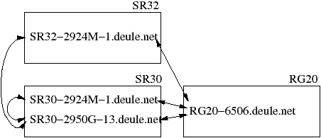
- Draw a figure which shows : the rooms (RG20, SR30 and SR32),
the four switches you have neighbor information about (using
their DNS names) and the connections between these switches.
Here we have a figure as requested :
- How many connections can be removed before this part of the
polytech'Lille network begins to fail (i.e. before some
machine will lose its connection to Internet) ?
Since the connection graph is a strongly connected component
with two cycles, you can remove two connections and still have a
connected graph. So two ethernet links can fail without leaving
a switch isolated from Internet. Note that is two connections
at most because if you remove the two connections
to SR32-1 it will no longer be connected to the
network.
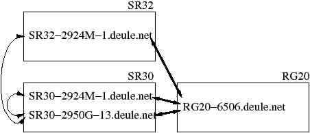
- Are all the connections equivalent ? If not, use a method on
the figure to stress this fact.
No. Some links are gigabit ethernet connections and some
are mere fast ethernet connections. On the figure below
the gigabit links are stressed by bolder lines.
23.3 Un peu de théorie
Avant la théorie il vous faut connaitre les adresses ethernet de
certains commutateurs dans les locaux SR30 et SR32 :
SR30-2924M-1 :  00d0.58fb.6b40
SR30-2950G-13 : 000a.8a5a.f2c0
SR32-2924M-1 :  00d0.58f5.2b00
SR32-2924M-5 :  0004.c152.ccc0
Nous allons maintenant pouvoir appliquer l'algorithme du spanning
tree sur la partie du réseau de Polytech'Lille que nous sommes
en train d'étudier. Pour ce faire répondez aux questions suivantes.
-
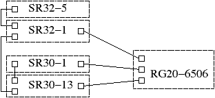
Draw a figure including the four switches of the previous
section. For each switch, draw a square box for each network
port connected to another switch. Last, draw a line between
boxes representing connected ports. To summarize, I want
a figure like the ones you have in the network course slides,
in the part about spanning tree.
The figure :
- Include in this figure the switch SR32-2924M-5, which has
no other connection to another switch than the one you may
discover in the previous neighbor lists (results of the
show cdp neighbors command).
The figure :
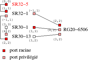
- Apply the spanning tree algorithm using the ethernet addresses
of the switches in order to choose the root switch. Choose the root
and the privilegied ports, using the number of
connections on the way to the root switch as a distance. If several ports are
at the same distance with this method, choose the port with the
highest bandwidth. Near each box representing a port write a
couple of distances : the distance to the root switch when the other
switch ports are disabled (-1 when the root switch cannot
be reached), and the distance to the root switch using the
root port of the switch.
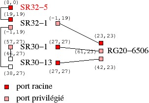
We have the MAC addresses of the five switches. We do not have any
information about the priority of the switches, so we assume that they
all have the default priority. Hence the switch with the lowest
MAC address is the root switch: the SR32-5 one.
The application of the spanning tree algorithm leads to the figure
below.
Note that there are two variants; you have the choice of the port
to be disabled on the link between RG20-6506 and SR30-13.
- Now apply the spanning tree algorithm using the sum
of the connection weights on the way to the root switch as a distance. Use the
same weights as in Cisco implementation : 4 for a gigabit connection
and 19 for a fast ethernet connection. As in the previous question,
write the couple of distances near each box.
There also are two variants, but this time it is because of
the link between SR30-13 and SR30-1.
23.4 Analyse d'informations sur le spanning tree
Voici le résultat d'une commande IOS tapée sur l'un des commutateurs
étudié dans ce sujet :
SR30-2950G-13#show spanning-tree vlan 1
VLAN0001
  Spanning tree enabled protocol ieee
  Root ID    Priority    32768
             Address     0004.c152.ccc0
             Cost        27
             Port        49 (GigabitEthernet0/1)
             Hello Time   2 sec  Max Age 20 sec  Forward Delay 15 sec

  Bridge ID  Priority    32769  (priority 32768 sys-id-ext 1)
             Address     000a.8a5a.f2c0
             Hello Time   2 sec  Max Age 20 sec  Forward Delay 15 sec
             Aging Time 300

Interface        Role Sts Cost      Prio.Nbr Type
---------------- ---- --- --------- -------- --------------------------------
Fa0/1            Altn BLK 19        128.1    P2p
Fa0/2            Altn BLK 19        128.2    P2p
Gi0/1            Root FWD 4         128.49   P2p
Gi0/2            Desg FWD 4         128.50   Shr
Après analyse de ce document, je vous propose de répondre aux questions
suivantes.
-
Does the above command output give you any hints about the
result of the execution of the spanning tree on the Polytech'Lille
switches for VLAN number 1 ?
Yes, all the blocked ports are on the switch SR30-13 (those
marked BLK). There is no need to have a look on the other switches, blocking two
ports is sufficient to remove all loops with this configuration.
- Is this practical result in accordance with the theorical
result obtained in the previous section (explanation
required) ?
This pratical result is one of the
two variants found in the last question of the previous section.
- In the practical result, is the root switch choice optimal ?
To answer this question, assume that all the connections between
the five switches are gigabit links. In this context and in the worst
case, how many ports of the main switch can be disabled by the spanning tree ? Hint : consider
your first use of the spanning tree in the previous section.
Take a look to the theorical result for the first application of
the spanning tree in the previous section. If all links are gigabit,
there are four variants (because, this time, each port of switch
SR30-1 may be disabled, since they are equivalent).
In the worst case variant, two links from the main switch are
disabled (the one to SR30-1 and the one to SR30-13).
It is quite a poor choice, since an important part of the trafic will
be commuted by less powerful switches, while the main switch will
mostly be idle.
- Give a method to force the spanning tree to use the main switch as its root
switch. I do not want a theorical solution but a practical one with the
corresponding IOS commands.
Just issuing the command
spanning-tree vlan 1-4094 priority 30000
on the main switch would do the trick.
23.5 Analyse de paquet
Voici un paquet récupéré par un utilitaire similaire à ether sur
une machine de l'école :
01 80 c2 00 00 00 00 08 7c 3d 94 06 00 3c 42 42
03 00 00 00 00 00 80 00 00 04 c1 52 cc c0 00 00
00 1b 80 01 00 08 7c 3d 94 00 80 06 03 00 14 00
02 00 0f 00 00 00 00 00 00 00 00 00
Répondez aux questions ci-dessous.
-
Give the source MAC address of this packet and the destination
MAC address.
The source addresse is 00:08:7c:3d:94:06 and the destination address
is 01:80:c2:00:00:00
- The destination address is special, in which way ? explain your
answer.
The low order bit of the high order byte of the destination
address is set to 1. This indicate a multicast ethernet address.
This packet is sent to several machines.
- Is this packet an IPv4 one ? an IPv6 one ? an ARP packet ?
something else ?
The type field is under 1500, so this must be interpreted as the ethernet packet
length. This packet is not a packet generated by a TCP/IP stack.
- Could you find in this packet (without trying to analyse it) a piece of data
we already encountered in the previous sections ?
One may note that the MAC address of the root switch is included into
this packet : 00:04:c1:52:cc:c0.
- Considering your answer to the previous question, try to
guess the type of our packet.
This packet is a BPDU (Bridge Protocol Data Unit). These packets are used
by switches to implement a distributed version of the spanning tree protocol.


